Sunday, 5 November 2017

Rendering and Decals


Hey, this is the 12th update on my SolidWorks blog

This week is about Rendering and Decals.

As the Lego Man has been completed, it’s now time to finish it off by rendering it in the desired colours and gloss finishes.
I decided to render my Lego man in similar colours to the Lego figure I have been using as a reference this whole time.
I picked the ‘red low gloss plastic’ and then in the appearance panel change the RGB colours so that I ended up with an orange for the arms and a maroon for the rest of the Lego man.


I then moved on to creating the Decals for the body of the Lego man, using the real Lego man as a reference. To save time I downloaded one of the faces provided by my lecturer.


Placing the body decal was pretty straight forward. When it came to putting the face on it was a little more difficult getting the exact location, so that it would be centred on the finished assembly. When I first placed the face decal on the head part it was on the back of the head in the assembly.  


Till next time,
Deanna (design student)

Tuesday, 31 October 2017

Lego Man Assembly


Hey, this is the 11th update on my SolidWorks blog

The Lego man has finally been completed, with a few struggles on the hand.

After completing the hips relatively easily I moved on to my final piece of the Lego man. 
I started off with a simple sketch of the hand to get the shape of the hand, at a closer look I realised that the part of the hand that goes in to the arm goes off on an angle. I decided that to get the right angle and shape I should scan the hand in and use the image as a reference. I then using the reference sketches started with the fingers and worked my way down.


After this I began to sub assemble the Lego man and finally go to put it all together.


Till next time,
Deanna (design student)

Sheet Metal


Hey, this is the 10th update on my SolidWorks blog

This Week was all about creating a box for the Lego man.

Creating a cardboard box for the Lego man to be presented in was a fairly simple process. It started off with a sketch of how the box would look like from the top, this sketch was then converted in to sheet metal.
Edge flanges were added to the side of the box to create tabs. Half of the box was complete and it just needed to be mirrored (when mirroring with sheet metal you cannot pick a plane to copy around).


After this an insert was created in the same way, this is for presenting the Lego man.


Till next time,
Deanna (design student)

Saturday, 7 October 2017

Lego Mans Arm


Hey, this is the 9th update on my SolidWorks blog

This week I was shown how to model the Lego man’s arm, as it is a complicated shape.

After watching the demo, I was completely lost and confused, there were so many steps.
I couldn’t remodel the arm from memory so I watched the video again and went along following each step. Staring by tracing the side view of the arm.


Then came the rest of the geometry for the construction. This lead to the fun part of creating new planes and lofting each section together.


Till next time,
Deanna (design student)

Lego Man


Hey, this is the 8th update on my SolidWorks blog

This week was the mid semester intensive and the start of the Lego man assignment.

I stared on the head, as it looked the easiest and would give me a little bit of practice using the Vernier Calipers (as I have not used them before).
I started off with extruding the main part of the head before extruding and cutting the top and bottom. To make the head a smooth curve I added fillets (the radius was estimated as it was hard to measure)


I then moved onto the left leg. Getting the basic shape and cutting out the hollow in the bottom was easy. I then ran into problems when I was cutting out the circles in the back of the leg. The top one would not cut out the way I expected/wanted it to. After rechecking the height on the leg and slightly adjusting it, the cut finally turned out the way it should look.


Till next time,
Deanna (design student)

Monday, 2 October 2017

Fillets, Chamfers, Lofts and Shells


Hey, this is the 7th update on my SolidWorks blog

This week was all about Fillets, Chamfers, Lofts and Shells.

The practical was pretty straight-forward. After creating the part, the Fillet (rounded edge) and Chamfer (flat edge) feature was used to add the final requirements. All that was needed was to change the size of the fillet/chamfer in the tool bar.


For some reason, this week I couldn’t get the volume of most of the part right. I double checked all the parts and couldn’t find the problem.


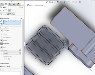
I also had great difficulty adding a Concentric Mate with two of the parts in the assembly.


Lofting a part required adding a new plane to loft the shape too, and also Guide Carvers so that the desired shape was created. When adding the guide curves, it was very important to pierce them through the base shape.


Till next time,
Deanna (design student)

Sunday, 10 September 2017

Assembly


Hey, this is the 6th update on my SolidWorks blog

This week was about learning how to use “Assembly” and a “Bill of Materials”.

I opened up my parts in the assembly after I created them and added copies of the parts to the assembly so that I could join them in different configurations by using “Mate” and different surfaces to “Mate” on.


I then went into the exploded view option so that I could drag parts from the assembly without losing their positon.


Last, I created a drawing of the exploded view but this time I inserted a bill of materials and used balloons to number match the corresponding parts to the bill.


Thank you for reading, until next time,
Deanna (design student)

2D Drawings


Hey, this is the 5th update on my SolidWorks blog

This week was about presenting CAD models as 2D drawings.

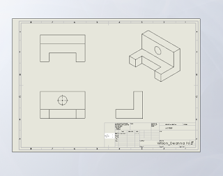
I started of with a standard title block and then edited it to contain my name and date. I also added in an extra column so that I could add in an image to show that my drawing will be in third angle projection.


After drawing my parts, I opened them up in “Drawing”. I placed my part down and moved the mouse around to display the top view, front view, right side and the isometric view. I then played around with the setting and turned on the hidden lines    


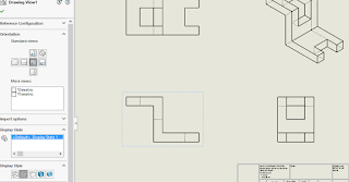
Next, I did a section view of a rounded part because the top and side view look the same. Also, there were details in the middle that needed to be shown. I proceeded to experiment with the hatching by making them parallel and on 45 degree angles.


That’s it for this week, till next time,
Deanna (design student)

Revolt Boss, Extrude Boss, Extruded Cut, Loft Base and Swept Boss


Hey, this is my 4th update on my SolidWorks blog

This week I have learnt about “Revolt Boss” vs. “Extrude Boss”; “Extruded cut”; “Loft Base”; “Swept Boss” and how to create a “New Plane”. For once, I didn’t have any problems and didn’t get stuck on any of the exercises!

“Revolt Boss” is a pretty cool tool as you draw a section of your object around a centre line and when you click ok, it extrudes your sketch around the centre line.


To get the same part as I got with “Revolt Boss” by just extruding (with “Extrude Boss”) is a little bit more time consuming. This is because I ended up with more features in my tree; since I needed to create each different sized piece individually and extrude each one to the right length.


“Extruded cut” is just the reverse of “Extruded Boss”. I thought it was pretty self-explanatory, all I needed to do was draw the shape I wanted cut into/through my shape and it was done.


“Lofted Base” tied in with creating a new plane. “Lofted base” is simple, I just needed to create a shape on one of the planes and then make a new plane by going to: reference, geometry and then plane; and then putting how far you want the plane. On the new plane, I drew a circle and then ‘Lofted’ the two shapes on the different planes together.


“Swept Boss” required me to draw on two planes. One was to get the overall shape and the other was to determine what size/shape was to follow the first shape. This creating a bendy pipe.


Till next time,
Deanna (design student)